
XCOMP -- Hard Disk Controller
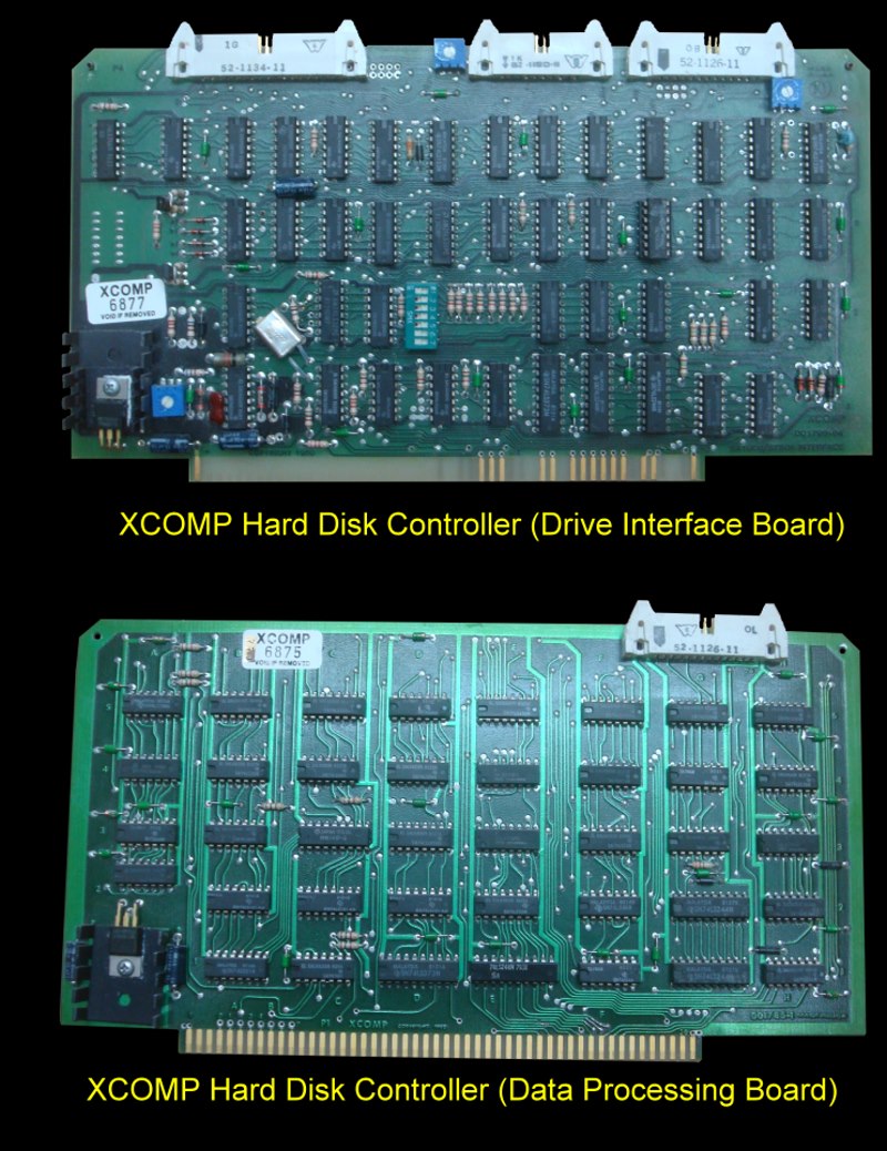
The controller consisted of two S-100 boards connected together with a cable
at the top right of the board. One board was used to interface with
the hard disk(s) and connected to the hard disk via two cables. The other
board actually processed the data and fed it to the system CPU via
the S-100 bus.
This XCOMP hard disk controller was in fact a set of boards with a different
drive interface board for each type of drive. It featured great operating
power in a compact, two S100 PC board package. The micro-programmed data
board processing was common to all controllers and operated with a second
drive interface board. They efficiently control a wide variety of drives
including the following HD interfaces:
• SMD (Storage Module Drive
• 5440 or 2315 cartridge
• ANSI disk bus
• Shugart SA-1000
• Shugart Technology ST-500
Additional interfaces could probably also be accommodated.
The board had the following features.
• A custom micro-programmable
processor to provides high performance.
• Feature multibank writable control memory for ultimate
flexibility.
• Maximum data integrity was maintained with a separate
header field for each disk sector.
• Support software available for a number of popular
operating systems, CP/M included.
• Fault isolation software for controller testing runs on
host computer.
The key to the XCOMP controller was its custom micro-programmable processor
which controlled data transfers. Custom microcode, provided by XCOMP, was
stored in writable control memory to accommodate specific drives. This
approach generated three major advantages: easy adaptation to the myriad of
drives by changing only the I/O driver software, simplified testing of the
controller by fault isolation software run on the host computer, and very
high performance.
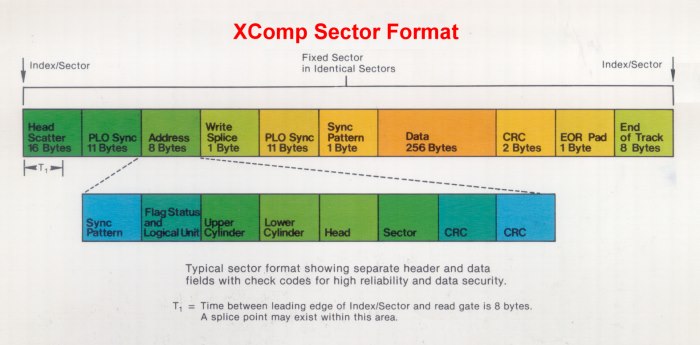
A sector format of separate header and data fields was used, each having
sync and check characters. By testing the header for correct head, cylinder
and sector before Reading and Writing on the data area, total data security
was assured without the time consuming separate Read operations to determine
correct head position. Average Read or Write operation latency time was only
one-half revolution.
These controllers use a 256 byte sector format and had a full sector buffer.
The logical sector format allowed interleaving which maximizes system
performance. The design eliminated problems with interrupt response time and
with bank switch systems under CP/M3 and MP/M operating systems. The buffer
was used in "look ahead" mode for increased system performance.
SPECIFICATIONS
• Buffer size - 256 bytes
• Disc data rate up to 10 MHz
• 8 BIT bus transfer
• Capable of 6 MHz IEEE operation on S100
• Separate header with 2 byte check code
• I/O addresses - any 8 address block on even boundary
• The board could be used in programmed I/O or interrupt
mode
• Interrupts could be jumper to any level
• Interrupts were generated on seek and/or data transfer
complete
XComp actually had 4 variations of the above boards and software. They are
referred to in the documentation as:-
SG/S If you
were using the above board with a Shugart 8" SA1000. (The extra pins on the
top left accommodated the larger cable connector. I have an SA1000 and one
day will try it out. The transparent cover where you can see the disk and
heads is real neat!
ST/S If you
are using a 5" ST506 hard disk and the above board.
They also had a ribbon cable/board arrangement where the second board was in
the disk drive rather than in the S-100 bus.
SG/S If an
8" SA1000 was used with this arrangement
ST/R If a 5:
ST506 type drive was used.
The software supplied was extensive and very well done. It's important
to realize that the data processing board has its own microprocessor that
needs to be fed specific "micro-code" to have it do something. Once these
bytes of data are sent, the board comes alive and carries out the required
function. The board is completely I/O mapped using a block of 8
ports. The default is 78H to 7FH.
XComp supplied source code to setup your system. Amongst the list was the
following Z80 programs.
SAATS Tests seek logic on the board
SAFMT Format and verify the hard disk.
SAIOS A BIOS driver for CPM V2.2
SAROM An example of a bootstrap ROM based loader
SARDT Random Read/Write diagnostic test
SARWT Read/Write diagnostic test
XSBT Test the onboard RAM buffer on the board.
I intend to extensively document this board/software in the future since it
is the basic HD board I use in my own S-100 system using CPM+, CPM-86 and
MS-DOS. This will however be a few months away. For now I am just
including the source code XComp supplied.
XComp HD Controller Files (.Zip
Format)
The sales brochure for this controller can be obtained
here.
The manual for this board can be obtained
here
The schematic for the two above boards can be obtained
here.
A short summary of XComp software can be obtained
here.
This page was last modified
on
01/08/2011